Part 4: Multi-Tile Displacement Mapping/Shader Assignment
Multi-Tile UV Mapping/Displacement Part 4
By Brian Freisinger
June 9, 2012
(This tutorial is designed around Maya and Mudbox. Several of the concepts here can be transposed into other 3d software packages that have UV grid control)
This is a continuation of the multi tile UV mapping tutorial.
Click on the images to enlarge for more detail.
To understand how to layout the ‘tiles’ for maya and mudbox please refer to Multi-Tile UV Mapping Part 1
Here we will cover both how to use displacement with multi-tile UV mapping, as well as an alternate method of assigning multi-tile color.
Why 32 bit?
(if you already use 32 bit and don’t want a history lesson you can skip to the ‘how’ part)
First off, we’ll discuss 32 bit displacement vs 8 or 16 bit.
I highly recommend using 32 bit .exr format for anything you’ve done custom sculpting on in Mudbox or Zbrush.
8 and 16 bit have a variety of problems, so does .tif format.
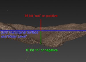
The main problem with anything less than 32 bit is it only goes in a single normal direction. I.E. it’s only 16 (or 8) bit in or out.
What’s this mean? If you sculpt a landscape and have hills and valleys, and export a 16 bit, it’s either going to have only the hills or the valleys. To get both you’d need two 16 bit maps, one for the positive normal values (the hills) and one for the negative (the valleys)
32 bit will handle both at the same time, so we only have a single file to work with.
Another pitfall to 16 bit or less is the need to adjust the map to display correctly. The user may need to shift the displacement +/- to get it to render 1:1 as expected from the sculpt.
32 bit knows about this internally based off the scale of the object, so it’s simply assign and render to get the same levels of displacement one would expect to see based off your sculpt.
IMPORTANT:
Because 32 bit does recognize the scale of the object you started with, change the scale AFTER you’ve sculpted and extracted displacement maps can have unexpected and mostly undesirable effects on your displacement render.
Scaling the object up will reduce the displacement amount to almost non existent, and scaling an object down will result in it looking ‘exploded’ or blown up.
So before painting a 32 bit displacement map it is very important to ESTABLISH THE SCALE OF YOUR OBJECT. If you paint on an object that is 5 cm across only to find out it needs to be 5 meters in the scene will cause some problems for you.
There are some workarounds using Nuke to change the scale, and it is possible to scale up and object in mudbox and then re-extract if a mistake is made, but it’s better to start with a properly scaled object.
Last thing. Mudbox saves an LZW compression tif. Bluntly this is horrible. Maya won’t read it, so you need to take it into Photoshop (which clamps your 32bit map and ruins the high/low details) or into Nuke to save it out in a non-compressed format. The EXR format saves properly, is lighter than tif and retains far more fidelity to the original sculpt.
In my personal opinion the whole .tif format is horrible. I use .png for color and .exr for displacement.
Ok, we’ll now move on to the how.
Extracting the displacement map.
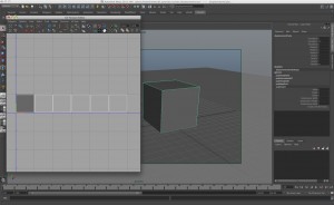
Using the same cube and six tile UV layout from part 1 we’ll paint a quick displacement map in Mudbox.
Two quick protips here:
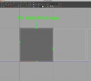
One it’s good practice to ‘bleed’ your UV map at least 5% away from the edge of the 0,1 grid tile.
The reason here is mudbox might return some errors in the edge of the displacement if it doesn’t have some room for bleed calculations. This also applies to multiple shells in a UV tile. If you have several UV maps separated out in a single tile you should have space between each shell to get a good extraction.
Two, as discussed before double check your scale before exporting an object to mudbox.
My cube is 5 cm in XYZ for this tutorial.
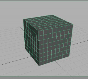
I am also going to pre subdivide the cube now so it keeps it’s ‘cubeness’ instead of turning into a sphere on subdivision.
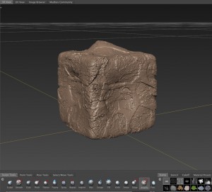
I did a quick displacement sculpt in Mudbox, nothing to fancy just enough to get the point across.
The point of this is to get the sculpt detail and the highs and lows to show up the same in our render.
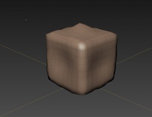
Another catch is mudbox has a nasty habit of effecting the base model when you’re sculpting.
So if we look back at our level 0 model we can see the high and low peaks I sculpted in are in the ‘zero’ level model.
I don’t know if this is a bug or a feature, but it’s a problem. You have two solutions here.
One is to export this model and use it as your new base mesh in Maya.
I do this often.
But in the event your model is so far down the pipeline this isn’t possible then I suggest the following.
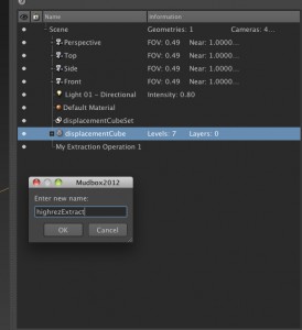
Select your sculpted object and rename it to something like ‘highrezExtract’ or similar.
Next in the same scene import the original pre sculpted object.
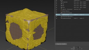
You should now have two objects in your scene. One you sculpted and the original one you exported from Maya.
The yellow object is the selected ‘high resolution sculpt, the other is the one I started with by doing a Maya OBJ export.
Now we need to extract the displacement maps.
For mudbox that’s: Maps -> Extract Texture Maps
Obviously we’re doing displacement.
But because we have two objects we’re going to do a ‘difference’ between the two. So when we select our models we’ll want the original in “Target” and the high resolution in “Source”
This is why renaming them is handy. To know which goes where without confusion. Extraction can take a long time, so minimising mistakes is handy.
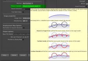
We also have to use the “Ray Casting” method because we’re doing a compare/difference between the two.
One thing of note here:
I want to extract a 32 bit map with both in and out, so I need to make sure “closest to lowres mesh’ (i.e. closest to target) is selected. This will look both inside and outside the mesh.
There are several other tricks and settings in mudbox for getting a good displacement map out, but they can be found in tutorals all over the web, so I’ll leave that to you.
One little trick though is figuring out your search distance. I know my cube was 5cm so I want to make sure my search distance goes out beyond that since I sculpted “out” quite a bit.
I eventually made the search distance 1.0 so the high peak on the top wouldn’t clip.
Another quick tip:
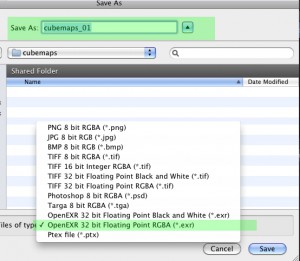
I named my file cubemaps_01 not cubemaps_v01
A lot of people like to put a v for ‘version’ behind their file iterations. While not a bad practice it can come back to haunt you with Mudbox. Mudbox uses v and u to siginify which UV tile it belongs to (see previous tutorial)
So if I had named this cubemap_v01 instead I’d get a file outputs that said:
cubemap_v01_u1_v1.exr, cubemap_v01_u2_v1.exr, etc
Not only is this confusing on a quick glance when you need to assign your maps to the shader, it will also confuse mudbox if you need to reload your maps back onto a mesh in mudbox (Sculpt using map). Mudbox won’t be able to figure out what map belongs to what tile. So I strongly suggest not using the ‘v’ or version letter for your displacement maps.
Also use the OpenEXR 32 bit floating Point RGBA file type, not the Black and White.
I can’t speak for other programs, but Maya has a problem reading the Black and White.
My maps are now extracted (I did 4k maps for detail)
As we’ve seen in the previous tutorials, I have six maps with coordinates exported (one for each tile)
Now we’ll need to create a shader to render these in Maya.
I’m using Vray, but this technique works for Renderman, Mental Ray or almost any other render engine on the market.
Creating the multi tile displacement shader
In my previous tutorial for color maps I used the layered texture shader. I’ve actually moved away from this because, well it sucks. I’m currently using the “plusMinusAverage” node for both my color and displacement.
The main reason here, is the layered texture shader in addition to being rather buggy, also does not respect negative values.
That means anything you paint going ‘IN’ won’t show up or worse show up as ‘clipped’ when you render. That’s a huge problem.
So the solution is to use the +/- average node.
That node will come in handly later, but lets start by setting up our shader.
I’m using Vray here so I’ll create a Vray shader. But if you’re using another render engine the principle is the same.
I need to set up/create a displacement node that’s hooked into my shader.
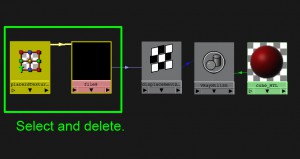
for Vray I need to go to the SG (or shading group) and create a file node.
What this is doing (for Vray) is creating a vray native displacement node.
Again, if you’re using Arnold, Renderman, MentalRay, etc, hook your displacment node up.
Once I’ve created it I actually delete the file node itself. I just need the displacement node to hook into later.
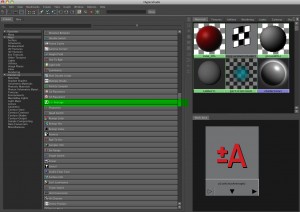
Next we’ll create a luminance node.
(NOTE: If you’re using this technique of plus/minus Average node instead of a layered shader for color maps DO NOT use the luminance node or it will change all your color maps to black and white)
This is the big trick to getting Maya to recognize negative values in a multi tile displacement set up. Without this node we will have our displacement all going “out” but nothing going in. So best case scenario it won’t look exactly like the sculpt, worst case it’ll clip and you’ll have smooth artifacts in the render. So save yourself pain and make a luminance node.
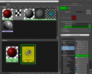
So if we go back to the displacement node we made, we’ll be replacing the file node we deleted with the luminance node. The easiest way to do this is just middle mouse drag the luminance node into the Displacement field of the displacement node.
If you use the connection editor it’s the ‘outvalue’ of the luminance node to the ‘displacement’ of the displacement node.
Now we’re going to use the +/- Average node we looked at earlier.
So create a “+/- Average” node and then middle mouse drag it to the “Value” field in the “Luminance“ node.
In the connection editor it’s the “3DOutput” of the +/- Average node connected to the “Value” of the Luminance node.
Now we’ll need to create slots in our +/- Average that will connect with our multiple displacement files.
This tutorial has 6 files, one for each side of our cube, so we’ll need to create six “slots”
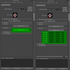
So, select the +/- Average node you’ve created and go to the attribute editor.
You’ll see a field called Input 3D, and the option button to “Add New Item” if you click on this 6 times, you’ll now have six fields ready to be connected.
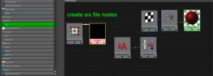
We’ll now need six file nodes to hook up to the Input 3D field
There are a few things we’ll need to do with the file nodes next. A lot of these were covered in the previous multi tile color mapping tutorial, but we’ll go over them again.
Open the Attribute editor of your first file node.
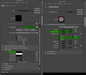
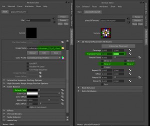
FIrst I’ll load my first displacement map in which is cubemaps_01_u1_v1.exr
Next I’ll make my Default Color a solid black. If you fail to do this with either color maps or displacement maps you’ll get some rather undesirable effects. Because the node we’re using is additive we don’t want any other color introduced. I’ll spare you the long story, but just make sure you’re set to solid black. If you render looks weird, double check you did this.
Next we’ll go over the the place2dTexture node which is attached to the file node you made.
In here we’ll have a couple things to change.
Because this is our first map the “Translate Frame” values are left alone.
Mudbox numbers it’s first tile u1_v1, but in Maya it’s u0_v0
No, I have no idea why they do this.
Wrap U and Wrap V need to be unchecked. We have multi tiles, so we want one per tile at this point.
Just so we’re clear, I’ll load up my next file which is cubemaps_01_u2_v1.exr
So you can see I loaded in cubemaps_01_u2_v1.exr
I made sure the default color was black (you have to do this for every node)
And in the place2dTexture node I’ve turned off the Wrap U and Wrap V again.
The Translate frame field is now set to 1 and 0
I’ve shifted it over 1 tile in u space, and none in v space.
u1_v1 was 0 and 0
u2_v1 is 1 and 0
A tile such as u5_v3 would be a translate value of?
4 and 2
It’s easy to loose track of this stuff when you have a lot of displacement tiles to keep some notes and double check your work often.
So do this for the last 4 file nodes. The should number up to 5 and 0 in Translate Frame
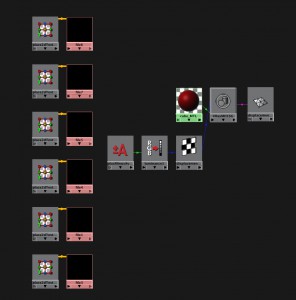
Your hypershade should now look like this
We’ll now need to hook up the file nodes we created to the +/- average node.
Remember the six slots we made in the +/- Average node Output 3D field?
The file nodes will get attached to those.
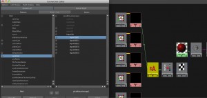
Open the connection editor (Windows->General Editors->Connection Editor)
Select the first file node and click “Reload Left” on the connection editor.
Select the +/- Average node and click “Reload Right” on the connection editor.
Now select “outColor” in the left column.
Expand the Input 3D fields by clicking the + sign and you’ll see the six fields we created earlier.
Select the first field “input3D[0]”
We’ve now established the connection between the file and the +/- Average node.
We’ll see the line appear in the hypershade showing the connection.
Now it’s a simple matter of doing this for the next 5 file nodes.
Just click on the next file node in the hypershade and click “Reload Left” in the connection editor again. Hook the next file nodes “outColor” to the next free field, “input3D[1]
Etc etc.
The connection order to the +/- Average node isn’t important.
The order of how they’ll read in render has already been established by the Translate Frame field in the place 2dTexture node.
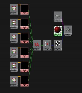
When everything is finally hooked up your hypershade graph should look similar to this.
Make sure your shader is assigned to your object, also make sure you’ve flagged whatever subdivision surface attribute your render engine has for the object otherwise you won’t see very much.
Now we’ll render the scene.
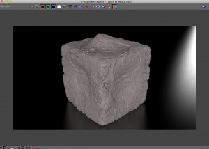
Success. It looks identical to the sculpt.
Basic troubleshooting for renders that don’t work.
Do I have the right files hooked up?
Did my displacement extractions actually work properly? (view them in Nuke or Photoshop to check)
Do I have my tiles and default color set correctly?
Did I remember to hook up a Luminance node.
Is it all piping into the correct displacement node.
And that’s it. Enjoy your multi tiling displacement.




Thanks! This tutorials was verry helpul!!
many thanks !!!!!!! helpful
Saved my life!! I’ve been banging my head against the wall trying to use the layered texture node in conjunction with 32bit displacement. Thanks a million!
Best tutorial on the internet about 32bit displacement in Vray! It helped me a lot:)
On small note: I was using a method where my texture’s alpha gain was 100 instead of 1 because the object had been scaled. Your method above will not work when using this trick. (So working in real scale is indeed a must!)
Thanks a milion
Marcus
Yeah, the alpha scale won’t work, so what I recommend doing is bringing the displacement map into “Nuke” or a similar post package and do a color correct function. Bring the Gain up by the amount the object was scaled (i.e. it was scaled 78.5%, so in the gain you’d put 78.5)
Basically ‘fix’ the displacement scale then use this method.